I'm in the process of making some LED tail lights for my car. I'd like to use an MSP430/TLC5940NT combo to control not only PWM brightness but also some interesting sequencing for show purposes.
I'll will do my best to explain everything. I'm not sure where to start in designing what I want so I hope posting this will get someone interested in helping me out.
I already have some MSP430G2331s and a ton of TLC5940NTs for this project.
The LED strings already have an inline resistor and will be powered by a voltage regulator (Sharp 9V LDO).
Car has seperate brake/turn signals on the rear so the rear signals do not need PWM brightness control.
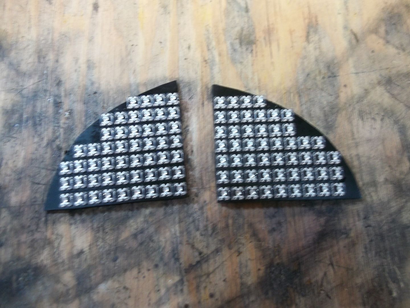
First let's start with the brake lights.
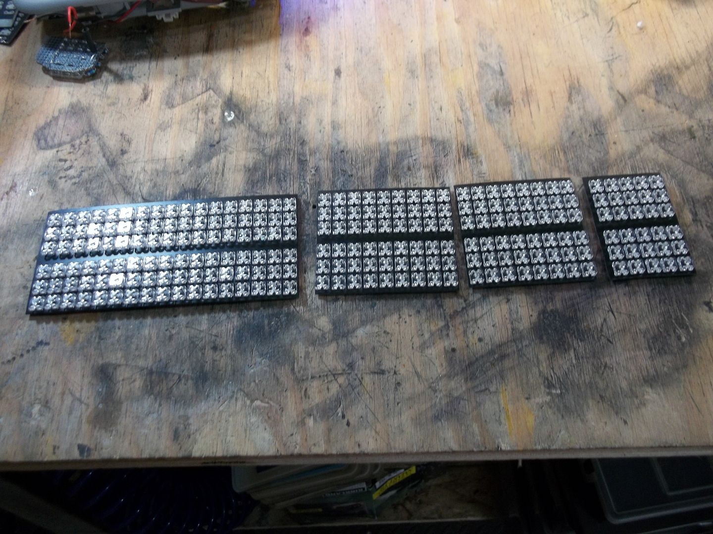
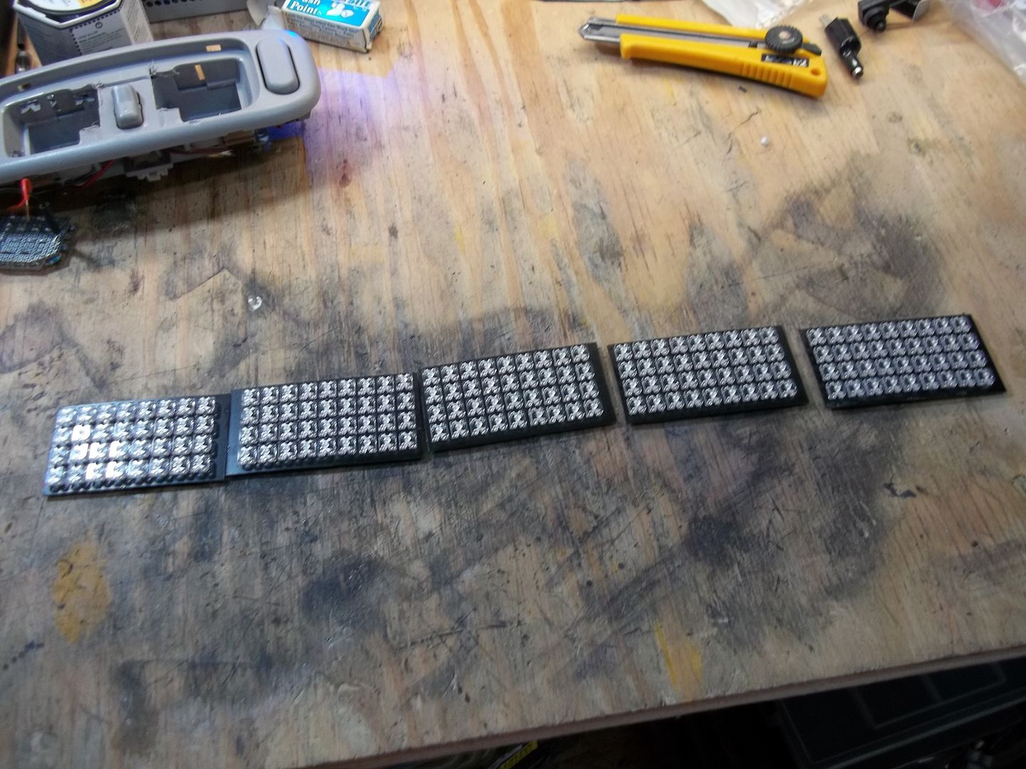
Here's a picture of the tail light boards, I'm still working on finalizing the final board so there is 5 in total.
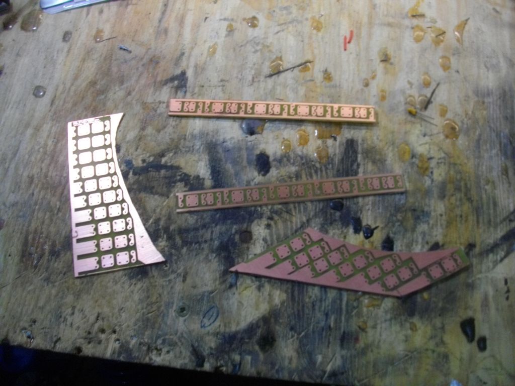
Back of a board.
There's 3 LEDs per string, so I was thinking of having each of these being 1 channel on the sequencer. I could however tie two (on above the other) together with a jumper if it will make things easer.
Using my current idea for the channels I'm looking at this for a channel break down.
Board 1 - 34 Channels
Board 2 - 18 Channels
Board 3 - 16 Channels
Board 4 - 10 Channels
Board 5 - 16 Channels
Total of 94 channels so 6 TLC5940s per side.
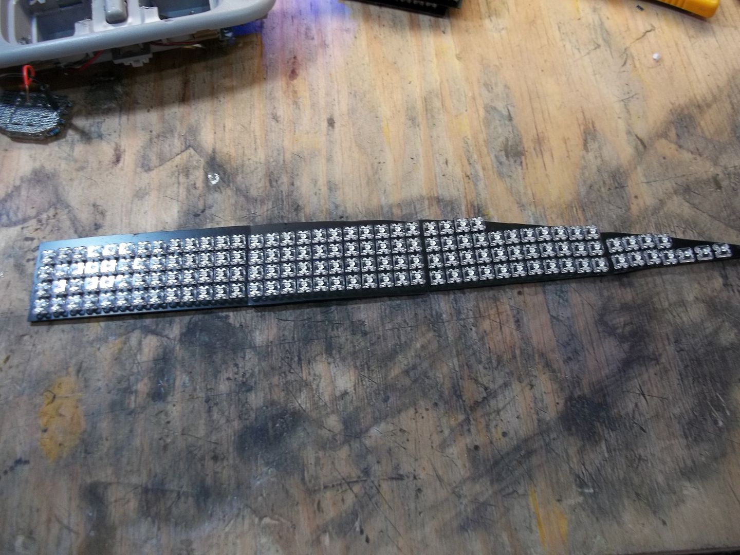
There is also a center section which I want to light up, I'm in the process of redesigning the boards for this part.
Here's a picture of my previous design of the boards to give you an idea.
Channel break down for this.
Board 1 - 12
Board 2 - 9
Board 3 - 5
Board 4 - 5
Board 5 - 5
Board 6 - 9
Board 7 - 12
TLC5940NT count - 4
Uc Functions for the Brake Lights
- All uCs of the brake light must communicate with each other for the sequencing
- Must take brake and marker signals from the OEM wiring.
- PWM brightness control for the marker lights
- Multiple show sequences (Cylon scan, Knight Rider, Strobe, etc)
- Possible - G sensor for strobe before solid on under panic braking
- Possible - Bluetooth connection to change between sequences
- Some sort of display up front so I know what the tails are doing
Rear Turn Signals
Channel count
Board 1 - 13
Board 2 - 11
Board 3 - 16
Total of 40 channels, 3 TLC5940s.
uC Functions for Rear Tails
- must take turn signal input from OEM wiring
- sequencial turn signals
- No marker so they operate at full brightness
- Multiple show funcntions
- Possible - Bluetooth connection to change between sequences
- Some sort of display up front so I know what the tails are doing
Front Turn Signals/Markers (Headlight and bumper)
Bumper markers
Board 1 - 13 Channels
1 TLC5940 per side
Headlight boards
Board 1 - 15 channels
1 TLC5940 per side
uC Functions for Front Markers/Turns
- Must take turn and marker signals from the OEM wiring.
- PWM brightness control for the marker lights
- Multiple show sequences (Cylon scan, Knight Rider, Strobe, etc)
- Possible - Bluetooth connection to change between sequences
- Some sort of display up front so I know what the boards are doing
Last set of boards
Name Plate boards
The car says the name across the back (Talon). I've made these boards to light up these letters.
I want 1 board to be 1 channel, again inline resistors and powered by a seperate voltage regulator.
uC functions for name plate boards
- PWM brightness control
- Take factory marker input
- Fade on/off
- Multiple Show functions (Spell name, Flicker before them come on, etc)
I think that is it. I hope someone is able to help me out in figuring out/designing this, I realize it's quite the under taking but I want to make it work.
Thanks in advance.